Proving the Work Energy Theorem
Empirical Tests of Loop-the-Loop
Physics 2A
Melvin J. Vaughn, Instructor
Written by Dave G
Experiment Date: April 24,
2011
Report Date: May 8, 2011
Proving the Work Energy Theorem
Empirical Tests of Loop-the-Loop
Contents
1. Abstract............................................................ 3
2. Principles.......................................................... 6
3. Experimental Procedure........................... 9
4. Raw Data and Numerical Analysis...... 19
5. Results............................................................ 24
6. Discussion and Conclusion..................... 27
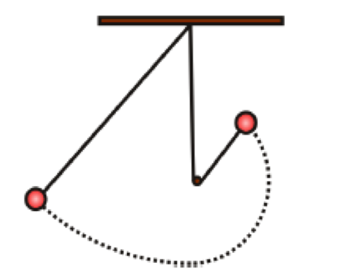
1. Abstract
This lab
report documents an experiment to empirically answer a quiz problem about
movement of a pendulum. The problem to solve is:
A pendulum is formed with a small ball and string
of length L. A peg is at height R above the pendulum's lowest point.
The question is, at what height H above the
pendulum's lowest point must the pendulum weight must be released for the
pendulum weight to swing completely around the peg, without the pendulum cord
going slack.
This picture illustrates the question:
The result of
this experiment is that expected, experimental, and actual results are
consistent within just over four percentage points. Calculations based on the
work energy, empirical test results from this experiment, and generally
accepted values found in textbooks, are consistent within just over four
percent:
\E1
Expected result:
Using work energy principles the computed result
is the minimum height H above the pendulum's lowest point the pendulum must be
released in order to circle the peg without the cord going slack, is 2.5 times
the value of radius R.
\E1
Experimental result:
The experimental result is the minimum height H
above the pendulum's lowest point the pendulum must be released in order to
circle the peg without the cord going slack, is 2.4 times the value of radius R.
\E1
Actual result:
Physics text books describing this and similar
loop-the-loop problems consistently show a height H equal to 2.5 times loop
radius R will allow the pendulum to circle the peg without the pendulum cord
going slack.
2.
Principles
There are three
principles pertinent to this experiment:
1. Conservation
of energy
2. Work
energy theorem
3. Relationship
between angular acceleration and weight of a body at apex of vertical rotation
1. Conservation of Energy
The principles of energy conservation state that total
energy in a system remains constant. Energy can be transferred from one object
to another but total energy is always the same. Work done by an applied force
that changes elevation, of an object such as a pendulum in this case, is
related to the work done by gravity and change in the object's kinetic and
potential energy.
2. Work Energy Theorem
The work energy theorem is used to prove
conservation of energy. Kinetic and potential energies in a system before and
after an event, such as linear or circular travel, sum to the same value.
The quiz problem was answered using work energy equations.
Work energy can be used to estimate velocity of an object at a given elevation,
elevations needed to achieve a certain velocities, and changes in kinetic and
potential energy after linear or rotational movement.
The work energy theorem is represented with the
following equation. It is used in this experiment to compute the expected value
of height H:
Energy before = Energy after
mgho
+ 1/2 mvo^2 = mgh + 1/2 mv^2
3. Angular
acceleration is at least equal to weight at the apex of rotation.
The problem to solve in this experiment is
similar to various problems seen in physics books commonly termed \D2loop the
loop\D3 problems. In these problems, an object travels a circle perpendicular to
the ground. At the apex of the circle, the object must have a certain angular
acceleration in order to complete the circle. That acceleration must equal or
exceed weight (mg) of the object. If this condition is not true, the object
will not successfully complete the loop.
\E1
If the object is a roller coaster car
on a track, normal force of the track on the car and weight both point down. If
the normal force is zero, meaning the track is not pushing on the car, then angular
acceleration is equal to weight. For the car to complete the loop, angular
acceleration must equal or exceed weight.
The equation representing this principle is
mv^2/r >= mg
\E1
If the object is a pendulum on a
cord, then cord tension must equal or exceed weight (mg). For pendulum cord
tension to equal or exceed weight, angular acceleration must equal or exceed
weight.
The equation representing this principle, in the
case of a pendulum on a cord, is mv^2/r >= mg.
3. Experimental Procedure
This section
describes what was done to complete the experiment. There are five steps in the
experimental procedure:
1. The
first step in this experimental procedure is compute the answer to the quiz
question using work energy.
2. The
second step in this experimental procedure is read and research the original
quiz question, and similar problems, in various different physics text books,
and determine whether there is a generally accepted solution to loop-the-loop
problems.
3. The
third step this experimental procedure is build a test fixture.
4. The
fourth step in this experimental procedure is run tests to experimentally
determine the answer to the quiz problem.
5. The
fifth step in this experimental procedure is analysis and interpretation of the
results.
Details of
each step in this experimental procedure are as follows:
Step 1 – Compute the value of H using work energy
The first
step in this experimental procedure is answer the quiz question using work
energy. The equation that is used to do this is:
1/2 mvo^2 +
mgho = 1/2 mv^2 + mgh
where:
\E1
initial velocity vo of the pendulum
is 0
\E1
h = 2r meaning final height H of the
pendulum, at the apex of rotation when the cord is taught, is twice the value
of R
\E1
cord tension at apex of the loop
around the peg, to complete a loop around the peg, without the cord going
slack, is equal to or greater than pendulum weight. This means:
o mg
= mv^2/r at h
o v^2
= gr at h
o v=sqrt(gr)
at h
The original
equation can then be written and simplified as:
mgho = 1/2
mv^2 + mg2r
(h = 2r)
mgho =
1/2mgr + 2mgr
(v^2 = gr)
ho = 1/2r +
2r = 2.5 r = H (cancel
m and g from all 3 terms)
The result of
this step in the experimental procedure is an expected value of height H, and
is shown in the computational procedure steps to be 2.5 times radius R of the
circle described by the pendulum circling the peg.
Step 2 - Reading and research
In this step
of the experimental procedure various physics textbooks are read and reviewed
with the objective of finding problems similar to the original quiz problem.
The books will show different perspectives on the same types of loop-the-loop problem.
There is consistency in use of work energy and a conclusion that height H is
2.5 times radius R.
Consult the
following textbooks:
\E1
Applied Physics,
by Dale Ewen, Neill Schurter, and Erik Gundersen. Eighth edition. Pages
185-211.
\E1
Fundamentals of Physics,
by Jearl Walker. Part 1, eighth edition. Pages 140-201.
\E1
Physics, by Robert
Resnick, David Halliday, and Kenneth Krane. Part 1, fourth edition, pages
131-199 and the accompanying Selected Solutions guide. See also part 1, seventh
edition of this same book, pages 140-200.
\E1
Physics, by James S.
Walker. Volume 1, fourth edition, pages 216-253.
In each of
these books, read about similar loop-the-loop problems, how they are solved
using work energy, and the solution to the problem.
The result of
this step is values for H and R that are used as accepted results, to be
compared with expected and experimental results, and used to compute percent
difference and percent error.
Step 3 - Construct Fixture
The third
step in this experimental procedure is construct a test fixture. Follow these
steps:
\E1
On a 17 x 40 inch piece of plywood,
using a pen, draw a horizontal line along the short side two inches from the
edge.
\E1
Mark the center of this line. Impale
the center with a four-inch lag screw. This is the pendulum\D5s axis of rotation.
\E1
Mark one-inch intervals below the lag
screw for 24 inches. Drill a 2 cm hole precisely at the one-inch intervals.
Insert a nail that is 3 inches long and 2 cm in diameter in the first hole.
\E1
Inscribe and mark one-inch intervals
below the horizontal line along the left side of the board.
\E1
Inscribe and mark degrees of an
inverted semicircle, from a position equivalent to zero degrees on a unit
circle, through 270 degrees, and up to 180 degrees, using the axis of rotation
as the center.
\E1
Hang a 20.5 inch pendulum cord of 8lb
test nylon and a 0.125 ounce lead weight on the end of the four-inch lag screw
impaled at the horizontal center of the board two inches below the top.
\E1
Attach the board to a wall so it
stands perpendicular to the floor.
Construction
of the test fixture is complete.
Description
of the finished product:
The test fixture is essentially an inverted
protractor inscribed on a large sheet of plywood, with a pendulum suspended
from the center of the semicircle formed by the protractor. Degrees of a
semicircle, from 90 to 270 degrees, or from the positive to negative X axis via
the negative Y axis, are marked on the plywood board at ten degree intervals. A
scale at one-inch intervals is inscribed directly under the pendulum axis and
along the left side of the board. Directly below the lag screw at one inch
intervals are holes where a steel peg is inserted. The peg is 2 centimeters in diameter
A photograph and a diagram of the test fixture
are on the following two pages.
Step 4 - Find the experimental value of R
Having built the
test fixture, the next step in this experimental test procedure is run a
sequence of tests to answer the original quiz question and experimentally
determine the value of R.
Fourteen
tests are run, described as follows:
\E1
For each test, the pendulum is
released at a position parallel to the axis of rotation with the cord fully
extended. This position corresponds to 90 degrees on a unit circle. This
release position is along the positive X axis, with the cord extended, and
level with the pendulum axis of rotation.
\E1
The pendulum is first released with
the peg in a hole one inch below the axis of rotation, meaning that L is R plus
one inch. The pendulum swing is carefully observed for whether the pendulum
circles the peg with the cord taught. The
final position of the pendulum after a full swing is recorded and can be
seen in the recorded test results.
\E1
With each subsequent test, the peg is
moved down one inch and the pendulum was released again. Each time the peg is
moved down, R decreases in length by one inch. The farthest location of the
swing is recorded. The pendulum is carefully observed to see whether it circles
the peg with the cord taught. The result of each test is recorded.
\E1
After the first time the pendulum
swings a full circle around the peg with the cord taught, three more tests are
conducted.
1. The
first test is to simply repeat the test, releasing the pendulum from a level
that results in a full circle around the peg with the cord taught. The purpose
is to verify the finding.
2. The
second test is to raise the peg one half an inch and then observe the swing.
The purpose is to more precisely determine the value of R.
3. The
third test is to lower the peg to 13 inches below the axis, meaning R is now
7.5 inches, and test again. The purpose is to observe and record what happens.
The interesting result of this test is recorded.
Step 5 - Analysis of the numerical results
At this point
in the experimental procedure the experimental value of height H has been
established. In this step of the experimental procedure, the relationship
between experimental values of radius R and height H are computed. The
experimental, expected, and actual values of R and H are compared. Percent
error and percent difference are computed.
The
experimental process is reviewed for measurement errors in order to estimate a
margin of error. The process is also reviewed to look for areas of possible
improvement, unanswered questions, and new potential areas of investigation.
This
completes the experimental test procedure.
4. Raw Data and Numerical Analysis
This section
presents what was learned reading about loop the loop problems in textbooks, the
computation of height H using work energy, and data from tests to empirically determine
height H. The three sets of results are:
1. The
first result is the accepted value of height H, ascertained from review of
physics books.
2. The
second result is the expected value of height H, computed using work energy
theorem
3. The
third result is the value of height H, found by testing
1. Accepted value of H ascertained form
a literature search
The accepted value of height H, as gleaned
from reading various physics texts that describe loop-the-loop problems, is
2.5R.
2. Expected value of H computed using
work energy
The minimum
value for height H, of the pendulum, required to complete a full circle around
the peg, is 2.5 times the value or radius R, above the lowest point of the
pendulum's path. This result is computed using work energy. The computation is premised
on the principle that tension on the pendulum cord at the apex of circular
travel around the peg must equal or exceed pendulum weight.
The
calculation of height H is as follows:
1/2 mvo^2 + mgho = 1/2 mv^2 + mgh
where:
\E1
initial velocity vo of the pendulum
is 0
\E1
h = 2r meaning final height H of the
pendulum is twice the value of radius R
\E1
cord tension at apex of loop around
the peg, to complete a loop around the peg, without the cord going slack, is
equal to or greater than pendulum weight. This means:
o mg
= mv^2/r at H, and (cancel
m and isolate v^2)
o v^2
= gr at H, and
o v=sqrt(gr)
at H
The equation is
rewritten and simplified as:
\E1
mgho = 1/2 mv^2 + mg2r (h = 2r)
\E1
mgho = 1/2mgr + 2mgr (v^2
= gr)
\E1
ho = 1/2r + 2r = 2.5 r = H (cancel m and g from all 3 terms)
This means minimum
value of height H is 2.5 times radius of the loop formed when the pendulum cord
circles the peg.
3. Experimental value of H derived from
testing
The recorded
test results show a radius R value of 8.5 inches leads to the pendulum completing
a rotation around the peg with the cord remaining taught.
A nine-inch
radius was tested. The test failed, meaning R has a margin of error of half an
inch. There are three other sources of error. These four sources of error sum
to 1.5 inches. Details of this finding are in the summary and conclusion.
The value of height
H is 20.5 inches. Radius R for a successful rotation is 8.5 inches. H divided
by R is 2.4. H is equal to 2.4R.
5. Results
Test results prove
the expected and actual result within just over four percentage points. When radius
R is 8.5 inches, meaning 2.4R = H, the pendulum makes a full circle around the
peg with the pendulum cord remaining taught. The experimental result is 2.4R,
the expected result is 2.5R, and the actual result is 2.5R.
The result of
this experiment is that calculations based on the work energy are consistent
with empirical results:
\E1
The actual result from a literature
search is H=2.5R.
\E1
The experimental result based on
tests documented in this report is H=2.4R. The minimum height H above the
pendulum's lowest point that the pendulum must be released in order for the
pendulum to make it completely around the peg without going slack is equal to
2.4 times the value of R.
\E1
The expected result using work energy
principles is H=2.5R. This computed result is that the minimum height H above
the pendulum's lowest point that the pendulum must be released in order for the
pendulum to make it completely around the peg without going slack is equal to
2.5 times the value of R.
Percent error and percent difference
\E1
Percent error is actual less measured
over actual. The actual value of H=2.5R is taken from the literature search.
The measured value of H=2.4R is the experimental result to two significant
figures.
Percent
error = abs(2.5-2.4)/2.5 = 4.0 percent
\E1
Percent difference is measured minus
expected over the average of expected and measured. The measured value of H is
2.4R from the tests. The expected value of H is 2.5R, computed in this experiment
using work energy.
Percent
difference = abs(2.4-2.5)/((2.4+2.5)/2) = 4.1 percent.
6. Discussion
and Conclusion
Test Results
The results
of this experiment support principles of energy conservation and use of work
energy computations to prove energy conservation. The results show that work
energy theorem equations accurately predict an empirically provable result.
Work energy can be used to answer the original problem.
Experimental
test results and computed results agree with accepted values. Physics textbooks
with this kind of loop-the-loop problem use work energy theorem as the solution
tool, and show a result of H = 2.5R.
Sources of Error
The experimental
test result has sources of error relating to precision of measurement:
\E1
Calibrating degrees of a circle on to
the plywood board that is the test fixture. It is estimated the degree values
could be off by +/- 2 degrees
\E1
Calibrating the exact number of
inches below the pendulum axis where holes are drilled for the peg. It is
estimated the measurements could be off by +/- 1/8 of an inch.
\E1 Reading
inches below the plane of the axis of rotation the pendulum swings, as recorded
in tests 1 to 8. It is estimated this reading could be off by +/- half an inch.
\E1
Air resistance that the pendulum is
exposed to. Given the minimal size of the pendulum cord and weight it is
expected this error is very small.
\E1
The recorded test notes show that a
radius R value of 8.5 inches leads to the pendulum completing a circle around
the peg with the cord remaining taught. Nine inches was tested and the test
failed, suggesting the R value has a half-inch margin of error.
\E1
Measuring the pendulum cord length is
estimated to be accurate to within an eighth of an inch.
\E1
Consistently releasing the pendulum
from the same release point is estimated to vary by as much as one fourth of an
inch.
These
possible errors in measurement sum to an inch and a half.
Personal observations
The original
question appears to be a variation of a common question I have seen in a
variety of different physics textbooks. It seems to be something of a classic
question. It is commonly called a 'loop the loop' question. The same problem is
illustrated using a roller coaster that must safely run a full circle without
separating from its tracks.
A number of interesting
test results were seen during the design, execution, and analysis in this
experiment. Unfortunately there was not time to explore all the issues that
were encountered. Expanding the scope of investigation and refining measurement
techniques could improve the experiment.
How can this experiment be improved?
\E1
This experiment could be improved by
developing a more carefully calibrated test fixture. There were precision
errors in marking degrees of the angles, depth below the axis, and height of
swing. Using a smooth board, more precise measurement tools, and more careful
inscribing would improve precision.
\E1
Executing the test in a vacuum would
eliminate air resistance, which was not considered in calculations.
\E1
Capturing the pendulum swings on video
may allow more precise determination of exactly how high it swings.
\E1
Exploring and answering some of the
unanswered questions, listed below, will help improve the informational and
educational value of this experiment.
Unanswered questions
This experiment
raises more questions answers. Many interesting observations were made that are
not explained or understood. Further testing, investigation, and help from
other teachers and students could help improve the experiment by covering more
areas of investigation.
Some of the unanswered
questions raised by this experiment are:
\E1
With test swings when the pendulum
remained taught but did not rotate, how does the observed height compare to a
computed estimate and how would that computation best be done? See tests #1-8.
\E1
What further information can be
determined from the two tests where the pendulum rotated a full circle but did
not keep the pendulum cord taught? See tests #9-11
\E1
What is the explanation for the final
test, where R was reduced to 7.5 inches? The pendulum cord completely wound
around the peg and appeared to still have momentum. Why did this happen? See
test #13.
\E1
If the cord did not make it around
the loop, it did not go slack. What is the explanation for this result? The
expected result is the cord goes slack. See tests #9-11.
\E1
When the pendulum first made a
circle, the cord was slack. If the cord was slack, a circle was completed. The
cord never went slack on a failed attempt to complete a circle. Why this
difference in observed behavior? See tests #1-8.
\E1
The ratio of pendulum velocity at
apex and lowest point is of the circle is an interesting constant value. I
would like to better understand this mathematical relationship and the reasons
for it.
-- end of document --